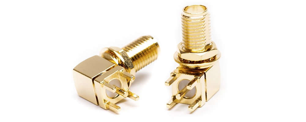
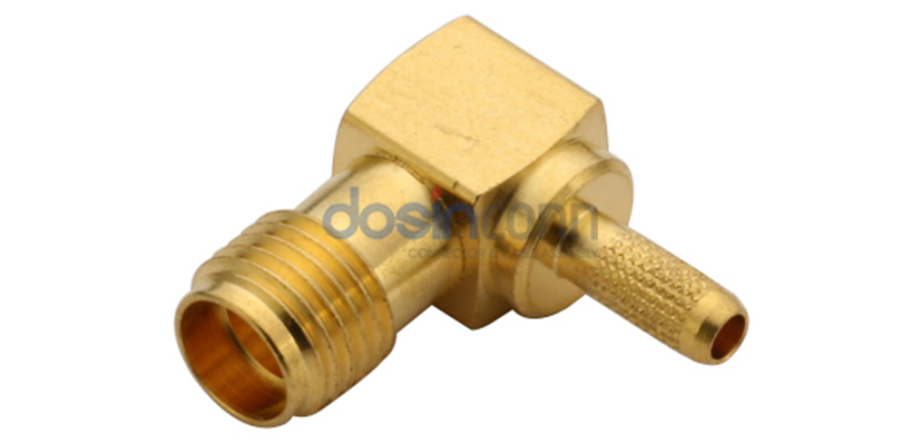
The SMA connector finds wide usage as a semi-precision, ultra-small RF and microwave connector, which is especially suitable for RF connections in electronic systems where frequencies can reach up to 18 GHz and even higher. SMA connectors are available in various forms, male, female, straight, right angle, bulkhead fittings, etc., making it possible to meet most requirements. The ultra-small size of the SMA connector enables relatively tiny electronic devices to use it.
Introduction of SMA connectors
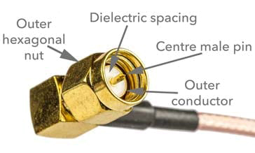
Bendix Scintilla and Omni-Spectra designed the SMA connector in the 1960s, initially using it for semi-rigid coaxial cables. It connects with a center pin formed in the coaxial cable’s center, eliminating the need for a specific connector center transition. The advantage of this connector was that it allowed the cable dielectric to contact the interface with no air gap directly. However, the disadvantage is that it requires more connection/disconnection. For applications using semi-rigid coaxial cable, the limitation on the number of connections is usually not an issue since it is a one-time fixed installation.
However, manufacturers have extended SMA connectors to other flexible cables and have introduced complete connectors with center pins. These high-standard manufactured connectors have an impedance of 50 ohms, allowing for a more significant number of connect/disconnect cyclesThe initial design of SMA connectors was for operation up to 18 GHz. Some versions have a top frequency of 12.4 GHz, and others specify 24 or 26.5 GHz. Higher frequency ceilings may require higher return loss operation.
With flexible cables, the cable usually determines frequency limits rather than the connector. This is because the cables SMA connectors accept small, and their losses are naturally much more significant than those of the connectors, especially at the frequencies they may be used. In some cases, the power rating of SMA connectors may be necessary. The critical parameter determining a mating coaxial connector’s average power handling capability is its ability to deliver high currents and maintain thermal rise to moderate temperatures.
The connectors have a threaded external connection interface with a hexagonal shape that allows tightening with a wrench. Using a special torque wrench, one can draw them to the correct seal, ensuring a good connection without over-tightening. The required torque is typically eight-inch pounds.
Basic parameters of SMA connectors
Resistance
Insulation resistance refers to the resistance value formed by applying a voltage to the insulating part of the connector and generating a leakage current. External factors such as insulation material, temperature, humidity, and contamination influence insulation resistance. The stated insulation resistance value of the connector usually refers to the index value shown under standard atmospheric conditions.
Safety parameters
Insulation resistance is the resistance value of the insulating part of the connector by applying a voltage to the insulating region, which causes leakage current within or on the surface of the insulating element. It is mainly affected by the insulation material, temperature, humidity, damage, and other factors. The connector sample insulation resistance value is generally provided in the standard atmospheric conditions of the indicator value. In some environmental conditions, the insulation resistance value will not have to decline. In addition, we should pay attention to the insulation resistance of the test voltage value.
Pressure resistance
Withstand voltage refers to the critical voltage that the mutually insulated area between the contact pairs or between the insulated area and the ground can withstand within a specified time than the rated voltage but will not produce a breakdown phenomenon. The distance and gap between contact pairs, their geometry, insulation material, temperature, humidity, air pressure, and many other factors mainly affect the value.
Flammability
During the operation of the connector, an electric current is essential, which also has the risk of causing a fire. Therefore, the choice of connectors needs to pay attention to its ability to prevent ignition and quickly self-extinguish the source of the fire. Insulation materials with flame retardant and self-extinguishing properties are essential when selecting electrical connectors.
Termination of SMA RF connectors
Cable Mount
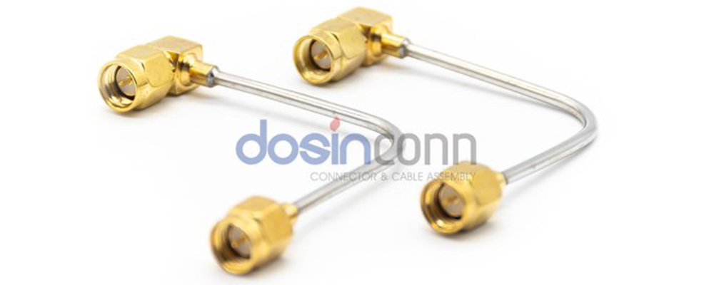
Wiring is also divided into solder wire and crimp connectors. Solder wire type is to solder the center conductor and cable shield. Crimp type is to crimp the center conductor and cable shield, crimp type efficiency and high-performance good. The solder wire type is stable and reliable—general, flexible cable is the more crimp-press type, and semi-flexible cable half steel cable is more welding type.
Panel Mount
Users generally use insert type or SMA connectors when connecting the connector to the PCB. Manufacturers mainly use gold-plate or tin-plate connector contact metal to ease tinning and achieve a stable connection with the PCB.