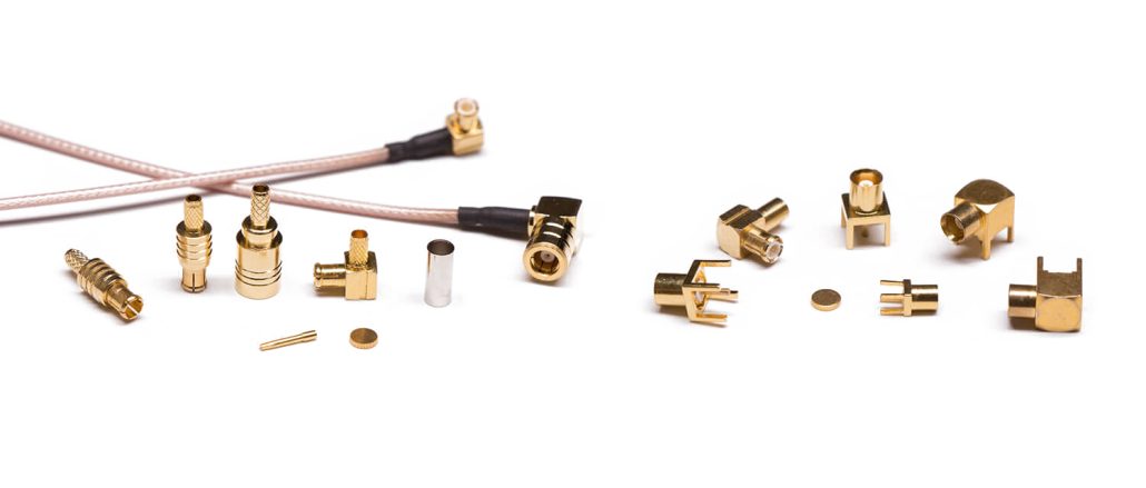
RF coaxial connector is used for high-frequency signal transmission, which has certain requirements in electrical performance, mechanical construction, and plating. When selecting a product, performance and economic factors must be considered to meet the system’s electrical equipment and value engineering requirements. The following are four areas to consider when selecting an RF coaxial connector:
- Connector connection method
- Electrical performance, cables, and cable installation methods
- Termination types
- Mechanical construction and plating.
Connector connection type
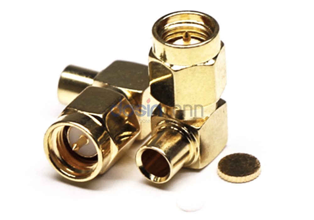
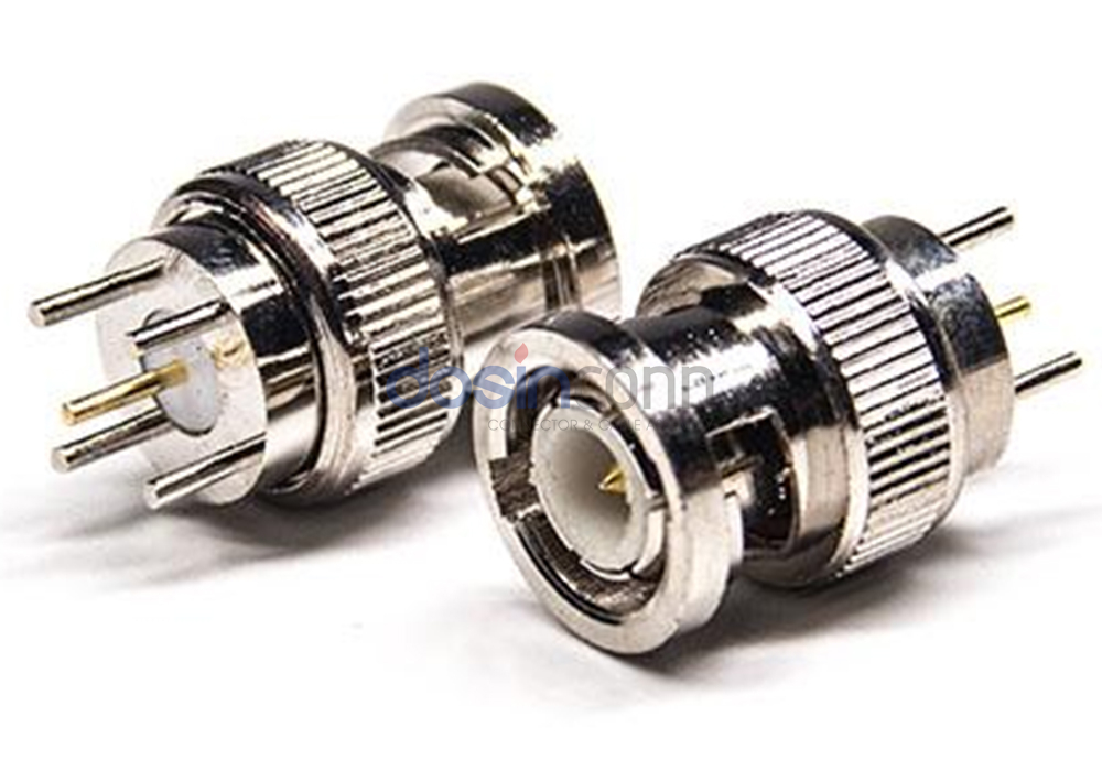
Threaded connection
Connectors with threaded connections often have larger contact sizes and are suitable for use in connectors working in environments with strong vibrations. People can equip this type of connection with a fuse to prevent loosening after completion.This type of connection is reliable but slow in connection and disconnection.
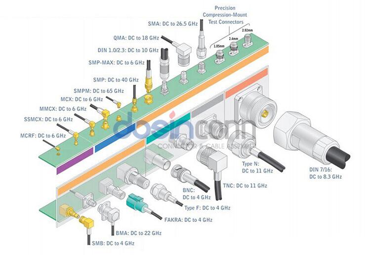
People widely use SMA connectors in aviation, radar, microwave, digital communications, and other Harsh Environment and civilian fields. When using 50Ω with flexible cable, the maximum usable frequency is 12.4GHz. It can reach 26.5GHz when using the semi-rigid cable, and SMA connectors with 75Ωimpedance have broad application prospects in digital communications.
TNC connectors have similar properties to BNC connectors except for threaded connections and still perform well under vibration conditions at 11GHz.
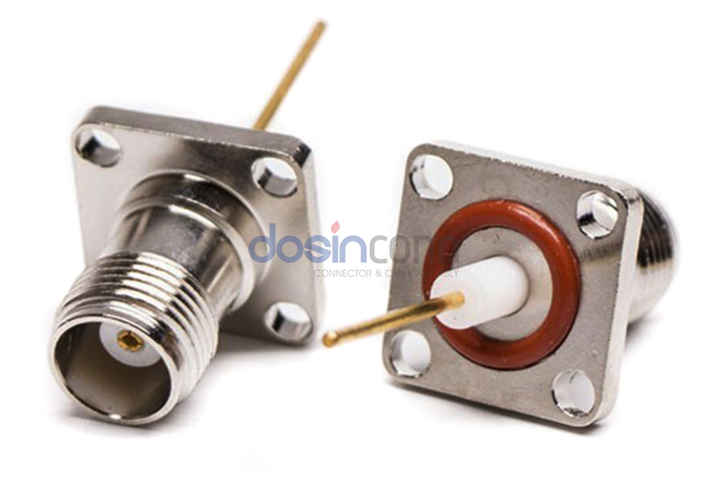
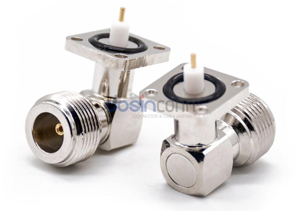
Typically, N-type connectors use air as an insulation material, have 50Ω or 75Ω impedance and can reach up to 11GHz. People commonly use them in area networks, media distribution, and test instruments. They are also an inexpensive option.
Bayonet connection
Bayonet connections are a reliable and rapid form of connection and disconnection. Bayonet-connected connectors mostly provide a visual indication of proper connection and locking through a small hole in the side of the male connector. People mostly use BNC connectors with bayonet connections for RF connections at frequencies below 4 GHz, and they widely use them in network systems, instrumentation, and computer interconnections.
Plug and Play Connection
Plug-and-play connections are a versatile form of connection. The connector plug and socket in the connection and separation of its direction of movement is usually reciprocal linear motion, does not have to twist and rotate, and only a small working space to complete the unloading. A common plug connection has a ball or pins in two structures. The connection form because there is no mechanical force-saving mechanism. Once the misplaced mechanical resistance significantly increases, it can be found in time.
SMB adopts a plug-and-play connection for quick connection. The most typical application is digital communication. For frequencies up to 4GHz, people use a 75Ω impedance, while for frequencies up to 2GHz, they use a 50Ω impedance.
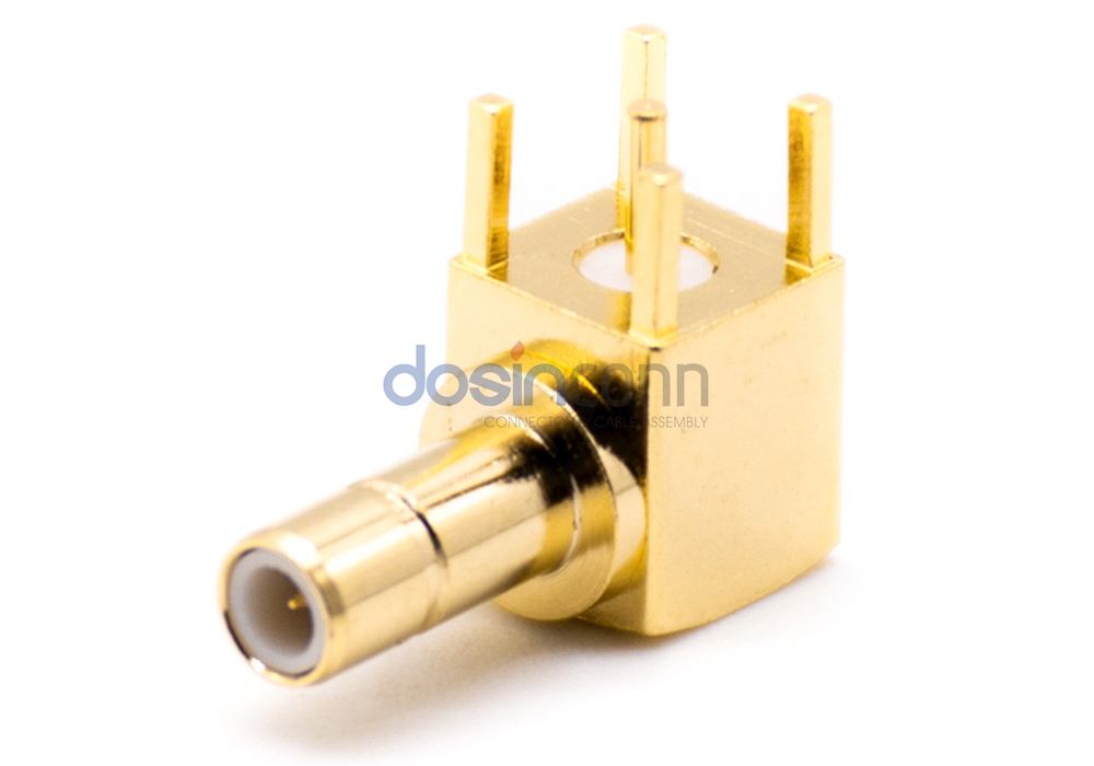
MCX and MMCX series also adopt plug-and-play connections. The connector is small in size and reliable in contact, which is the preferred product to meet the intensive and miniaturization, and has wide application prospects.
Electrical performance
Contact resistance: A high-quality electrical connector should have a low and stable contact resistance.
Insulation resistance: It measures the insulation performance between the electrical connector contacts and between the contacts and the shell.
Electrical resistance: Or voltage resistance, dielectric withstand voltage, is the ability to characterize the rated test voltage between the contacts of the connector or between the contacts and the shell.
Other electrical properties: electromagnetic interference leakage attenuation is to evaluate the connector’s electromagnetic interference shielding effect.
For RF coaxial connectors, there are also electrical specifications such as characteristic impedance, insertion loss, reflection coefficient, and voltage standing wave ratio (VSWR). Due to the development of digital technology, a new type of connector has emerged to connect and transmit high-speed digital pulse signals, namely, high-speed signal connectors. Accordingly, new electrical indicators, such as crosstalk, transmission delay, time lag, etc., have emerged regarding electrical performance and characteristic impedance.
Cable
TV cables are usually used in systems where the only impedance is considered due to their low shielding performance, typically in applications such as TV antennas.
Flexible cable is a variant of TV cable. It has relatively more continuous impedance and a better shielding effect that can bend, low price and is widely used in the computer industry. Still, it can not be used for systems requiring high shielding performance. Shielded flexible cables, conversely, eliminate inductance and capacitance and are mainly used in instruments and buildings.
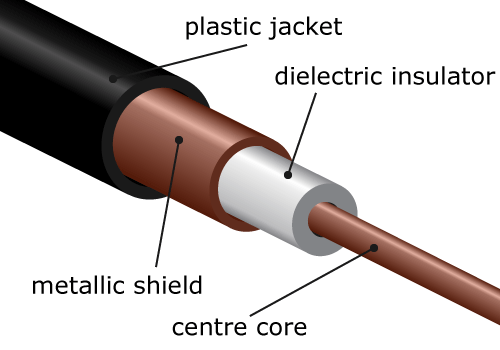
Flexible coaxial cables are the most common type of hermetic transmission cables due to their special properties. Coaxial means that the signal and ground conductors are on the same axis, and the outer conductor consists of an intricate braid, also called braided coaxial cable. This cable has a good shielding effect on the center conductor. In addition to the high voltage resistance, this cable is suitable for high-frequency and high-temperature conditions.
The semi-rigid coaxial cable replaces the braided layer with a tubular shell, effectively compensating for the poor shielding of braided cables at high frequencies. People usually use semi-rigid cables at very high frequencies.
Connector installation method
There are two main methods of connector installation: (1) solder the center conductor, and screw the shield. (2) crimp the center conductor, and crimp the shield. Other methods derived from the above two methods are soldering the center conductor and crimp shield.
The crimping method of assembly provides reliable termination and is highly efficient, and manufacturers design a special crimping tool to ensure identical cable assembly. In cases where no special installation tools are available, manufacturers use welded center conductors. As manufacturers develop low-cost assembly tools, the popularity of welded center conductor crimp shields is expected to increase.
Termination Types
Users can use the connectors for RF coaxial cable, PCB, and other connection interfaces.
Mechanical structure and the plating layer
The structure of the connector greatly affects its price. Each connector design includes Harsh Environment and commercial standards, Harsh Environment standards according to MIL-C-39012 manufacturing all-copper parts, PTFE insulation, internal and external gold plating, and the most reliable performance. Commercial standard designs use inexpensive materials such as cast brass, polypropylene insulation, silver plating, etc.
Manufacturers generally cover the center conductor with gold plating due to its low resistance, excellent tightness, and corrosion resistance. Harsh Environment standards require gold plating on SMA, SMB, in N, TNC, and BNC using silver plating, but because silver is easy to oxidize, many users prefer nickel plating. Commonly used RF coaxial connector insulators are Teflon, polypropylene, and toughened polystyrene, of which Teflon insulation performance is the best but has higher production costs.
RF coaxial Connector materials and structure affect the processing difficulty and efficiency of the connector, so users should, based on their application environment, reasonably choose a good performance-to-price ratio of the connector.