
Connector is a kind of electrical signal or mechanical force with the role of the circuit to connect, disconnect or switch the functional components, is to ensure the normal operation of various electronic systems, safe operation of the key components. In RF circuits, RF connectors mainly provide reliable signal transmission and connect different types of RF devices and components.
With the development of electronics and communication technology, the variety of RF connectors is becoming more and more abundant in order to meet the needs of various applications, which also places higher demands on the users. Connectors on devices like test ports and cables can often cause system failures in engineering applications. The improper use of these connectors can also result in inaccurate test data during activities such as calibration and testing. Proper use and maintenance of connectors can reduce the chance of damage, maintain their precision, and extend their life.
RF Connectors Basic Structure
The basic structure of RF connectors includes: the center conductor (positive or negative center contact); the dielectric material, or insulator, outside the inner conductor; and the outermost part is the outer contact, which plays the same role as the outer shield of the coaxial cable, i.e., transmitting signals, serving as a shield or circuiting element. According to the connection method, coaxial connectors have about the following categories:
(1) Bayonet type (internal bayonet, external bayonet);
(2) Threaded type (right-hand thread, left-hand thread);
(3) Push-in type (straight plug, with stop, self-locking).
Common RF Connectors
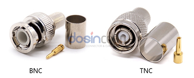
BNC and TNC Connectors
BNC connectors are available in 50Ω and 75Ω versions. 50Ω versions are designed to operate up to 4GHz. because BNC connectors generate noise under severe vibration, TNC connectors were developed in the late 1950’s. TNC is basically a threaded connection version of the BNC connector with a characteristic impedance of 50Ω and can operate up to 11GHz.
N-type Connectors
The N-type connector is one of the first connectors capable of correctly transmitting microwave signals. It uses a threaded connection and has a characteristic impedance of 50Ω. 75Ω versions are also available. The common characteristic impedance is 50Ω for N-type connectors, which can operate at frequencies up to 11GHz. Specially designed versions can operate at frequencies up to 18GHz.
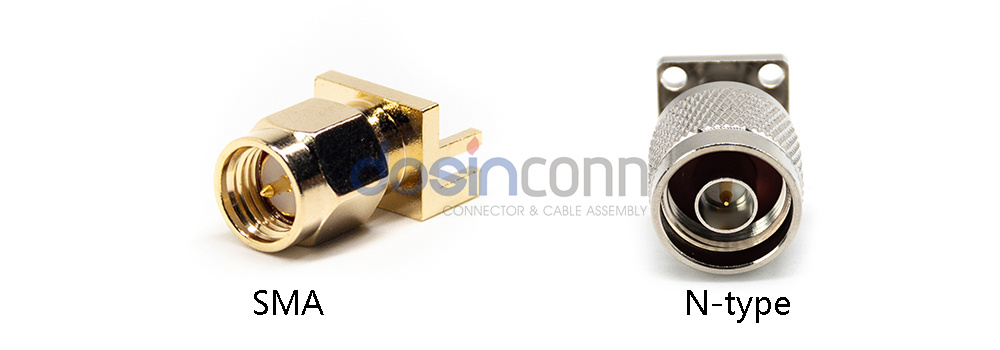
SMA / SMB / SMC connectors
SMA connectors, introduced in the early 1960s, offer a threaded connection and 50 Ω characteristic impedance. With precise versions able to operate at frequencies up to 26.5 GHz, they find application in a range of wideband microwave systems – including circuit-transitions on microstrip printed circuit boards and coaxial cable-to-waveguide transitions, as well as various microwave system components such as switches, filters, amplifiers, oscillators, and attenuators.
The SMB connector was developed because of the need for a mechanical interface for quick connection and removal of the subminiature connector. The SMB connector uses a push-in stop connection, making the connection easier and providing good performance under slight shaking.
SMC connectors have a design that closely resembles SMB connectors. They share the same structure of having a matching inner conductor and dielectric insulator, as well as a threaded connection that helps in positioning the conductor and insulator. The SMC connectors are effective in frequencies up to 10 GHz, with a 50 Ω design. Small dimensions and high vibration environments often require the use of SMC connectors.
5 mm/2.92 mm/2.4 mm/1.85 mm/1 mm Connectors
These coaxial connectors are named after the inner diameter of the outer conductor. 3.5mm connectors are dimensionally identical to SMA connectors and are physically more rugged, allowing thousands of reconnections and operating frequencies up to 34GHz. 2.92mm connectors, also known as K connectors, are dimensionally identical to SMA and 3.5mm connectors and operate up to 40GHz. 2.4mm connectors operate up to 50 GHz and have different thread sizes from 3.5mm/SMA/2.92mm connectors. 2.4mm connectors work up to 50 GHz, the thread size is different from 3.5mm/SMA/2.92mm connectors. 1.85mm connectors, also called V connectors, work up to 67GHz. 1mm connectors work up to 110GHz.
Precautions for use
Appearance Inspection
Inspect all connectors carefully before each connection. First, check the connectors for obvious defects or damage, severe wear on the plating, and scratches or indentations on the mating surfaces. Then check for deformed threads, bent, deformed or broken center conductors, etc.The mating surfaces need to be examined closely for contaminants such as metal or metal shavings. Any dirt or metallic particles on the mating surface is likely the result of placing the connector with the contact surface facing down or leaving behind oil and dust particles after touching it by hand. Using contaminated or damaged connectors will seriously affect their performance and may even damage the 2 connectors.
For APC-7 connectors, check the surface and edges of the spring-loaded sleeve of the center conductor for deformation or damage, and lightly press the sleeve with a round-ended wooden or plastic stick to see if it is flexible, rather than directly pressing it with a pencil lead or finger to avoid damaging the joint surface. When dealing with polarized connectors, particularly 3.5mm and SMA, it is crucial to give special attention to the contact claws of the center conductor for negative connectors since they are highly susceptible to damage or bending.
Selecting the Right RF Connector
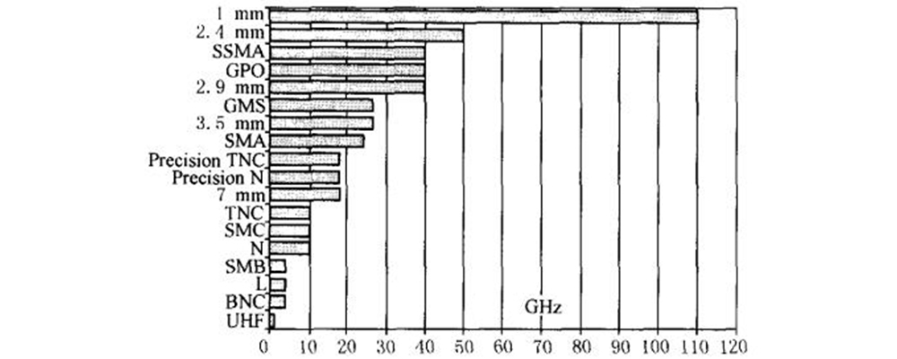
According to the working frequency band, characteristic impedance, transmission power size, insertion loss, etc. Select the connector to meet the requirements of use. Characteristic impedance is a very important basic parameter of the connector, it directly affects the voltage VSWR, operating band, insertion loss and other indicators. RF coaxial connector characteristic impedance is generally 50Ω or 75Ω, in the case of no special instructions usually 50Ω. The applicable frequency range of commonly used coaxial connectors, as shown in the figure.
In the need to use different types of connectors for transfer, should minimize the number of transfers to reduce reflections and insertion loss brought about by the measurement error. Pay close attention to the matching of connector sizes, for example, there may be a mismatch between the thread sizes of 2.92mm and 2.4mm connectors.
Connections
To prevent damage to the inner conductor of the connector, after successful docking of the inner conductor during connection, the female connector is typically secured in place while the nut of the male connector is tightened. It is important to avoid applying excessive torque perpendicular to the inner conductor during connection, as this can cause the contact claw of the center conductor of the female connector to bend or break.
Use of Torque Wrenches
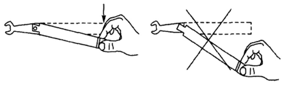
When fastening threaded connectors, the use of a torque wrench is necessary to ensure a consistent connection. Typically, torque wrenches have a distinctive notch or marking on their handle that indicates the desired torque setting. To achieve the desired torque, the operator must align this mark accordingly. The wrench end of a torque wrench is usually directional, with the hexagonal catch of the handle gripping the nut and the torque applied vertically downward. It is wrong to bend the torque wrench completely or to apply torque in the opposite direction.
Static Protection
When connecting any microwave components, connectors on the whole machine, be sure to pay extra attention to static electricity. Static electricity may directly damage the internal circuit devices of the instrument (such as amplifiers, mixers, detectors, etc.). If possible, you should operate in a static safe area and wear a wrist strap, the operating table arrangement of anti-static mats and has been grounded. Usually, before connecting any equipment, touch the metal casing of the test port with your hand, which can discharge the static electricity on your body.
Maintenance Methods
Connector contamination and damage will usually directly cause measurement errors, after the use of timely cleaning to avoid contamination and damage caused by dirt and metal particles, so as to ensure that the connector is in the best working conditions for a long time.
Compressed air is the recommended choice because it can safely remove tiny particles and dust without harming the connector joint surface. To remove stubborn dirt and grease from the connector plug conductor and center conductor, you can use a cotton swab dampened with isopropyl alcohol to gently wipe the surface. Be careful not to apply too much pressure and cause deformation, displacement or damage to the plug conductor. Additionally, make sure that the solvent does not come into contact with the insulation layer, as it could damage it. Allow the connector surface solvent to air dry for storage. RF connectors, especially for microwave band connectors should be covered with a plastic shield at the end of the mating surface when not in use to avoid contamination of the mating surface, preferably stored in a box with a foam groove arrangement to avoid mechanical damage.