
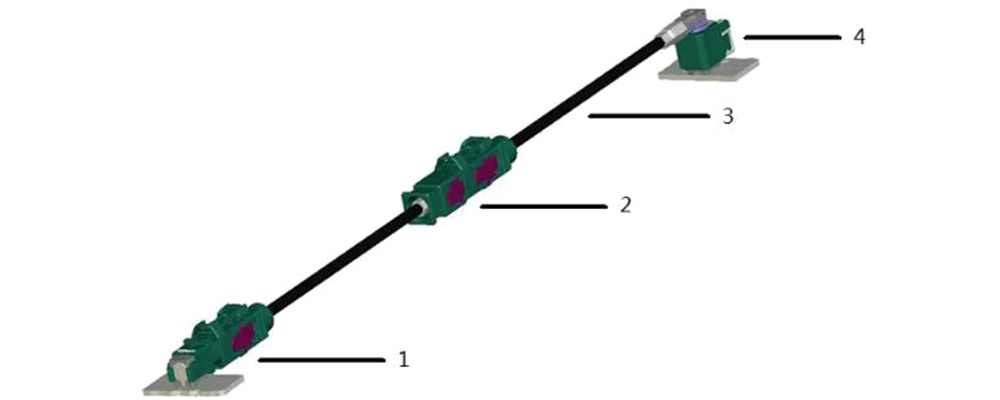
As the development of intelligent driving systems and in-car entertainment systems for automobiles continues, the transmission speed of in-car signals also increases, resulting in the need for higher frequency transmission cables. Fakra coaxial cable is a type of high-speed, high-frequency transmission cable that can transmit RF signals or high-definition camera signals. Its typical structure consists of Fakra connectors, Fakra inline connectors, coaxial cables, and PCB board connectors.
Return loss and insertion loss of Fakra coaxial cables are two important electrical performance parameters in parts matching and automotive applications. If these parameters are greatly impacted, it can diminish the quality of the signal being transmitted. This can affect how the user perceives the signal and may even result in functional malfunctions. The purpose of this paper is to explore the impact of Fakra connectors, Fakra Inline connectors, coaxial cables and PCB end connectors on the signal quality of the entire transmission link by analyzing their components and to propose engineering methods to reduce this impact.
Impact of Fakra connectors on transmission performance
Before analyzing the impact of Fakra connectors on signal quality, it is necessary to understand their design standards and analyze potential impact factors around the standards. interface dimension standards used for Fakra connectors are mainly ISO20860-1 and USCAR-18, while test standards include ISO20860-2, USCAR-17 and USCAR-2. These standards define The main dimensions of Fakra connectors in the axial and radial directions, which in turn cover both male and female connectors.
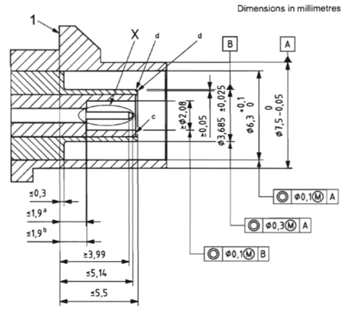
Certain dimensions have a tolerance range in the axial direction, resulting in a gap between the male and female connectors after insertion. The interface’s dimensional tolerances have resulted in a gap of a certain size that impacts the electrical properties. The size of the air gap affects the degree of impedance matching. Furthermore, the standard solely stipulates the design prerequisite of 50Ω, and various companies depend on different insulation dielectric materials in their products, which can consequently alter the impedance matching outcome. As a result, it is essential to confirm that the associated electrical performance metrics remain within the designated values by aligning connectors with differing insulation materials and interface structures, despite conforming to the standardized interface structure size.
Impact of Fakra Inline on transmission performance
In the process of connecting and assembling vehicle wire harnesses, Inline connectors are usually used to complete the docking. For example, when connecting the entertainment host to an external antenna, since the entertainment host is located in the dashboard area and the external antenna is located at the rear of the roof, it is necessary to use the wire harnesses of the instrument panel, body, and roof to complete the connection, which inevitably results in the use of Inline connectors.
Comparison of insertion loss of different samples
According to the comparison shown in the diagram: Sample 1 is a complete 400mm long with Fakra connectors at both ends; Sample 2 is four equal-length segments of 100mm long, connected in series through three pairs of Fakra Inline connectors.
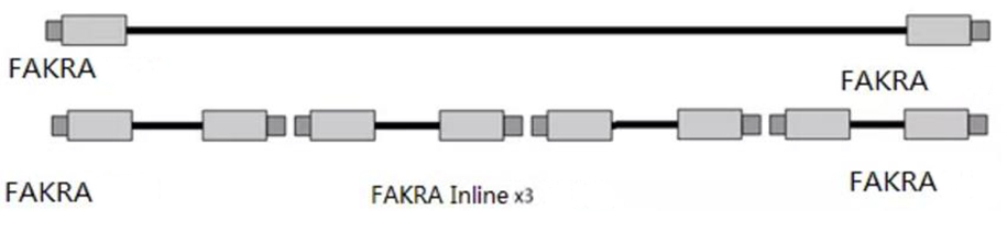
By comparing the insertion loss, it can be found that sample 2 has a higher insertion loss than sample 1 at the same frequency, due to the effect of the insertion loss of the 3 pairs of Inline connectors in the middle of the transmission link.
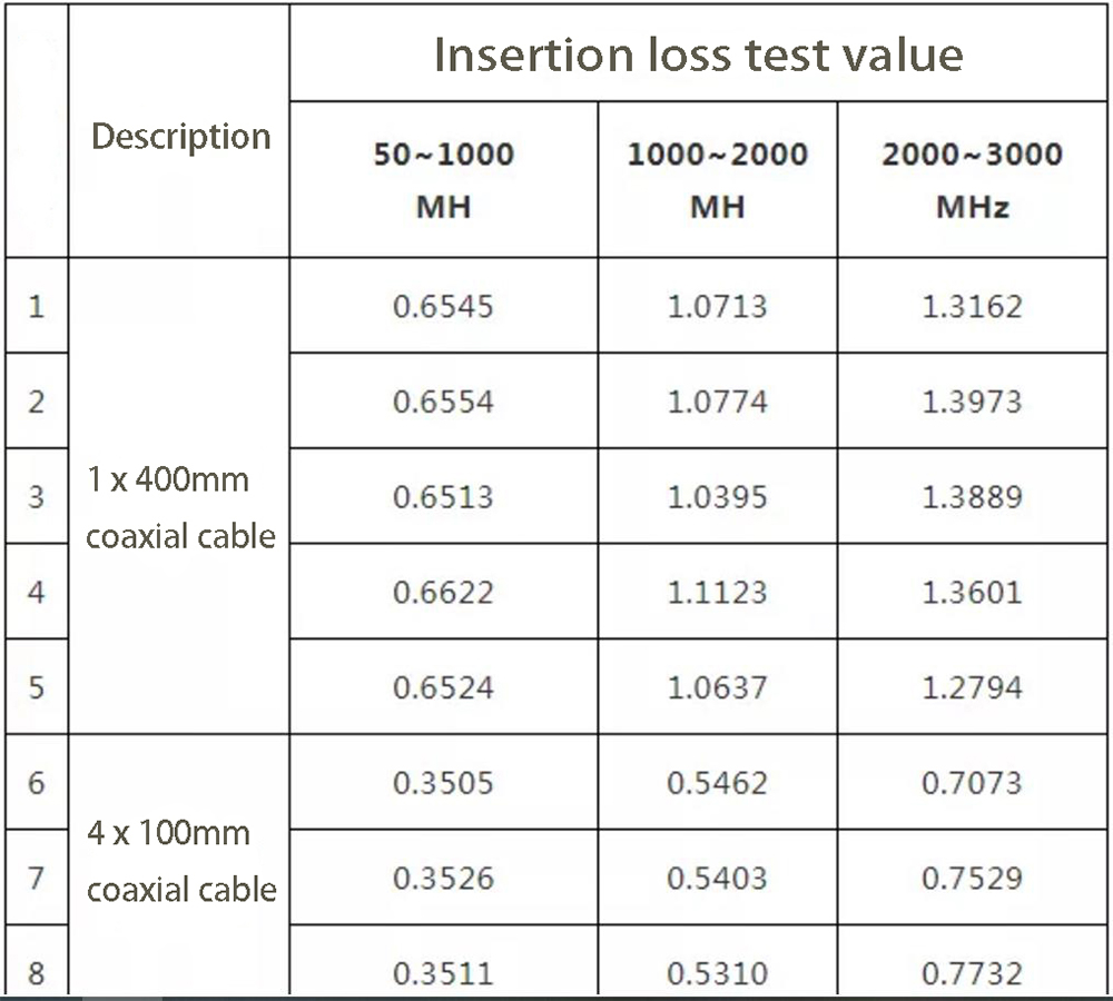
Based on the data, the inclusion of inline connectors results in insertion loss. This suggests that as the number of connectors increases, the extent of the loss becomes more severe. Therefore, when choosing inline connectors, it is necessary to consider their applicable operating frequency, because the insertion loss will also vary at different frequencies. At the same time, in practical applications, the quality stability and consistency of inline connectors need to be verified.
In addition, it is necessary to evaluate and test the Inline connections from different manufacturers to ensure the overall performance after switching. If the Inline connector is not properly matched, an impedient mismatch can occur. This can result in a return loss, a decrease in signal output power, and an increase in insertion loss. The conductor loss, dielectric loss and radiation energy of the connector can also increase the insertion loss, thereby reducing the signal output power.
Impact of Fakra coaxial cables on transmission performance
Composition of coaxial cable
Two cylindrical metal conductors with the same axis and insulated from each other are the basic units of a coaxial cable.
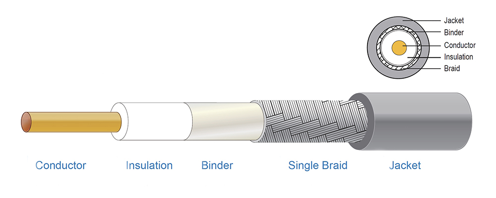
Conductor: the center conductor and the outer shield conductor.
Insulation material: Insulation material between the central conductor and the shield conductor.
Binder:Fixed cables to avoid tangling and cross-tangling between cables.
Insulation: the external shielding conductor and insulation material between the metal shield.
Jacket: the external sheathing material that protects the entire cable.
Influencing Factors
In general, the insertion loss of a Fakra coaxial cable is considered to be equal to the sum of the losses of the connector and the cable. However, the concentricity and contact condition of the pins and jacks also have an important influence on the insertion loss. Poor contact conditions may lead to increased insertion loss, signal instability or even open circuits. Methods to determine the contact condition include measuring the insertion resistance and insertion holding force, and ISO 20860-2 defines the test methods for internal and external conductors.
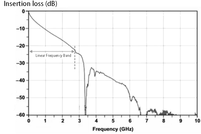
Another factor that affects insertion loss is the operating frequency range of the cable. The insertion loss test curve of a certain cable type shows that the test results vary linearly within the linear frequency band, while outside the bandwidth, the test results vary non-linearly and produce abrupt changes at certain frequency points, which have an important impact on the whole signal transmission link.
Impact of Fakra PCB connectors on transmission performance
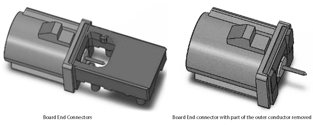
Compared to wire-end connectors, Fakra board-end connectors have structural differences at the interface, and the most common difference is the end-face design of the male end outer conductor. This includes two designs: insulation and air, and these two designs have different effects on performance when plugged into the female end connector.
In addition, another important factor in the performance of the male board-end connector is the connection design between the tail of the connector and the PCB board. For example, the structure diagram of a board-end connector with an internal conductor flat on a signal line on the circuit board, or the structure diagram of a board-end connector with part of the outer conductor cut off. These factors will affect the impedance matching of signal transmission, such as the root of the internal conductor of the board-end connector, the width of the signal line on the PCB board, the working bandwidth of the PCB board, and the size of the openings on both sides of the signal line on the board.
Therefore, when the operating frequency reaches a certain threshold, it is necessary to consider the board-end connector, the PCB board, and the corresponding welding parameters. Full demonstration of these factors is essential to prevent abrupt changes in high-frequency signals within specific frequency ranges.
Conclusion
According to the above content, when selecting Fakra coaxial cables, it is crucial to consider the operating bandwidth of the cables and connectors. The operating bandwidth of these devices affects the transmission of the signal. Additionally, in practical applications, it is necessary to select specially designed cables with lower loss and larger diameters, specialized waterproof and dustproof Fakra connectors, and Fakra connectors that meet vibration requirements based on the situation. It is important to confirm the consistency and matching of similar connectors from different manufacturers.
Overall, Fakra connectors and other related devices have an impact on the signal transmission chain. Through analyzing the factors that contribute to this impact and implementing relevant design and testing measures, the transmission of high-frequency signals can become more reliable and stable.