The Classification of RF Connectors
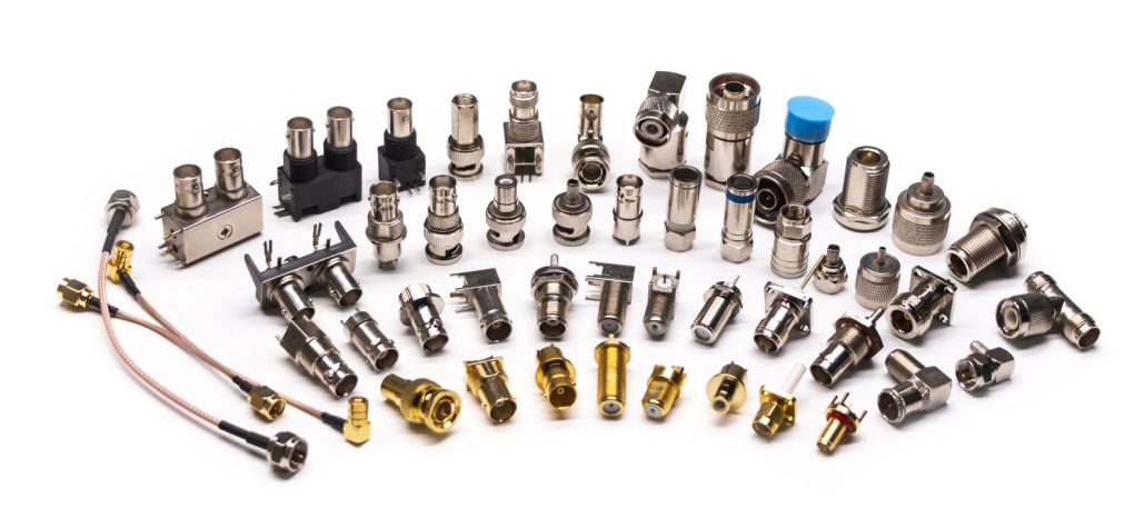
RF connector (RF coaxial connector) is a kind of electrical connector, generally with coaxial cable and the use. The shielding effectiveness of RF connectors is generally better. So RF connectors are increasingly used in RF products and digital circuits. But the RF coaxial connectors are very many types, and it is often easy to confuse. The following chart is a detailed picture, marking out the majority of the connector name and the corresponding frequency.

Of course, the frequency range of these markings also has a relationship with the manufacturer. Some may be better, and some will be worse.
You can also categorize RF connectors according to the interface structure and size.
1. According to the structure of the connection interface
- Bayonet type (internal bayonet, external bayonet): BNC.
- Thread type (right-hand thread, left-hand thread): L29 (7/16), N, F, TNC, SMA, SMC, SSMA, SSMB, FME, L9 (1.6/5.6), 7 mm, 3.5 mm, 2.4 mm, K-head (2.92 mm), 1.85 mm, 1.0 mm.
- Push-in (inline, self-locking): SMB, SSMB, MCX, MMCX, SMP, SMI, BMA, SAA.
- Flange connection type
2. Category by size
- Standard: UHF, N, 7/16, 7mm.
- Small size: BNC, TNC.
- Subminiature: SMA, SMB, SMC, MCX, BMA, SAA, 3.5mm.
- Miniature: SSMA, SSMB, MMCX, 2.4mm, K (2.92mm), 1.85mm, 1mm.
The Main Indicators of RF Connectors
Choose what type of RF connector, according to their actual application. Purely from the performance to choose words, you can judge according to its electrical performance indicators. The main indicators of RF connectors.
1. Impedance.
Almost all RF connectors and cables are standardized to 50ohm impedance. The only exception is the 75ohm connector for cable TV systems. RF coaxial cable connectors matching the cable’s characteristic impedance are also important.

2. VSWR (Voltage Standing Wave Ratio).
VSWR is commonly used by engineers to assess the RF connector as an indicator. It is the same as impedance. In general, within the frequency range of concern to ensure that the VSWR is less than 1.2. but not necessarily to reach 1.2. Some are in 1.5 or 2 below to meet the requirements. The lower, the better, the higher the cost will be.

3. Frequency Range
RF connectors work in the frequency range of high frequency and high-speed areas must be concerned. Frequency is divided into several grades, such as 1 ~ 6GHz, or 0 ~ 18GHz, 20GHz, 27GHz, 40GHz, 50GHz, 67GHz, 110GHz, or even higher.
4. Insertion Loss
Loss indicates that all connectors will be concerned. Usually, RF connector loss will be relatively small (if too large, indicating that there is a problem). Generally, the frequency range of concern is within 0.1 to 0.5dB.

5. Return Loss
In terms of some engineers doing digital circuits, VSWR is not so intuitive, so some will use return loss to characterize.

6. Use (Plugging) Times
Some engineers may not pay much attention to the number of times the connector is in use. The number of times this use is generally considered to be the number of times after plugging and unplugging, the connector’s performance will change. General RF connector plugging times are 500 or 1000 times. There will be higher requirements. If you want to do some experiments for this, we must carry it out under a specific torque/torque. Otherwise, it is difficult to ensure the number of times the requirements. I have used the connector and generally have not reached this number of times. It is estimated that it can use over 100 times or 200 times, and the internal core has deformed because there is always the possibility of inserting crooked or too much force and twisting.
| Connector Type | Operating Frequency(Max) | Outer conductor inner diameter | Outer diameter of inner conductor | Connection Life (times) | Thread Size | Coupling torque (N-cm/Ib-inch) |
|---|---|---|---|---|---|---|
| N Type | 18GHz | 7mm | 3.04mm | 5000 | 5/8-24 UNHF-2 | 135/12 |
| SMA | 12GHz | 4.13mm | 1.3mm | 500 | 1/4-36 UNS-2 | 56/6 |
| 3.5mm | 33GHz | 3.5mm | 1.52mm | 3000 | 1/4-36 UNS-2 | 90/8 |
| 2.92mm(K) | 40GHz | 2.92mm | 1.27mm | 2000 | 1/4-36 UNS-2 | 90/8 |
| 2.4mm | 50GHz | 2.4mm | 1.042mm | 5000 | M7*0.75 | 90/8 |
| 1.85mm | 67GHz | 1.85mm | 0.803mm | 5000 | M7*0.75 | 90/8 |
| 1.0mm | 110GHz | 1.000±0.005mm | 0.434±0.005mm | 3000 | M4*0.7 | 45/4 |