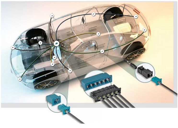
FAKRA coaxial cable is a kind of high-speed and high-frequency cable for transmitting RF signal or HD camera signal based on the very fine coaxial (MCC/SGC) cable. With the growing demand for intelligent driving systems and in-car entertainment systems in new energy vehicles and the increasing integration of thin and light products, the transmission rate of the corresponding in-car signal connection cables is increasing year by year. The traditional electronic cable-based LVDS signal cable can no longer meet the requirements.
The emergence of very fine coaxial cable (MCC/SGC) has solved this problem; it has many advantages such as small size, long life, good flexibility, stable impedance, and good shielding effect.
FAKRA is an acronym for FAchKReis Automobil (a team of automotive experts, consisting of engineers from BMW, Huber-Suhner, Rosenberger and other companies, before the Huber-Suhner-related connector business and technology merged into Rosenberger in 2010).
The FAKRA automotive connectors are designed for automotive applications; connectors that meet this antenna standard are called FAKRA connectors. The FAKRA coaxial cable is the one that meets the antenna standard by using very fine coaxial (MCC/SGC) cable and single wire wrap cable structure as above.
The typical structure as shown in the figure below. Mainly includes: 1. FAKRA connector, 2. FAKRA Inline connector, 3. Coaxial cable, 4. PCB board end connector.
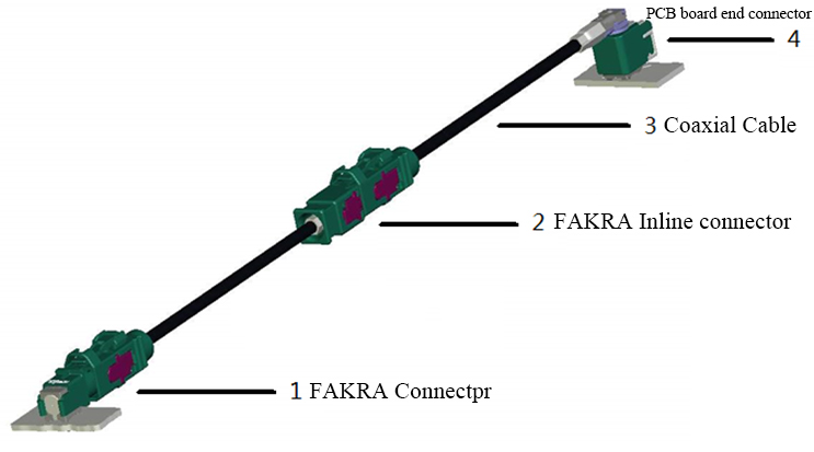
Fakra connector structure
They are generally applicable to RF signal connectors in the automotive industry, GPS positioning systems, satellite radios, in-car Internet access. FAKRA automotive connectors are designed for automotive applications. They are based on the SMB connector interface FAKRA (Automated Expert Group); creating a unified connector system and a standard that everyone will follow.
Due to their special standard locking system, FAKRA connectors meet the high performance and safety requirements of today’s automotive industry. FAKRA connectors are available in the rated frequency range of 6 GHz.
These connectors are widely available for GPS antennas, engine management systems, analog or digital radios, auxiliary heating, TV/video monitors, antennas, power distribution boxes, accident data analysis, cell phones, remote keyless entry systems, distance control, pressure control and navigation systems, etc.
FAKRA connectors are available in jack or plug type construction with impedance specification of 50 Ohm. FAKRA connectors are available in straight or right angle profiles as well as no-load types. These FAKRA connectors are terminated by crimping/soldering or soldering.
1、The overall structure of the board-end and harness-end connectors
Common Fakra connectors consist of plastic shell, outer conductor, center conductor, insulator, crimp sleeve (harness end connector only), and secondary lock (harness end connector only).
2、Secondary lock, color + mechanical error-proof
Secondary Lock: Ensures that the terminals are in place and increases the retention of the terminals. The secondary lock is usually purple.
Color + mechanical error-proof: There are structures to prevent wrong pairing design on the connector’s mating interface, and different error-proof structures have different color plastic shells corresponding to them.

FAKRA Basic Introduction
1、Performance parameters of Fakra connectors
According to the parameter requirements in IS0 20860.
The main electrical performance parameters: transmission frequency 0 ~ 4GHz; characteristic impedance of 50 ohms; maximum load current 1A
Main mechanical performance parameters: latch holding force ≥ 100N error-proof force ≥ 40N
2、Common applications
Wireless signal transmission: car AM/FM; GPS; car networking (2~4GHz, including transmitting), remote control, etc.
Video signal transmission applications: ADAS-based outbreak, mainly applied to cameras.
3、Related standards
Design standard: ISO20860; USCAR18
Verification standards: LV214; USCAR2; USCAR17
Defines the main dimensions of FAKRA connectors in axial and radial directions, including male connectors and female connectors
4、Waterproof performance
Using the waterproof version of the harness end connector, IPX7/IPX9K waterproof rating can be achieved at the connector-to-mate interface.
Rosenberger released the first generation of Fakra products in 2000 from the RF connector SMB interface based on the addition of plastic shell structure and came. The integration of the plastic shell makes Fakra products suitable for rapid assembly in vehicles and ensures stable and unbroken links.
The second-generation Fakra product optimized the design, clarified the interface standard performance requirements, and wrote the requirements into ISO20860-1 released in 2004.
The second-generation products are mainly completed by turning. Rosenberg released the third-generation Fakra in 2007, cost-optimized while maintaining the performance of the second-generation. The third generation is mainly machined by stamping (also by stretching) and is more suitable for fully automated production.

FAKRA Coaxial Cable
The anatomical structure of the coaxial wire can see from the inside to the outside: central wire, insulation layer, aluminum foil, braided shield, and wire outer skin. A coaxial cable is a composite consisting of two conductors. The center conductor of the coaxial cable is used to transmit the signal.
The metal shield plays two roles: first, as a common ground for the signal to provide a current loop for the signal; second, as a shield for the signal to suppress the interference of electromagnetic noise to the signal.
Center wire and shield mesh between semi-foamed polypropylene insulation. The insulation layer determines the transmission characteristics of the cable and effectively protects the intermediate conductors.
As the name implies, coaxial wire consists of layers of insulation wrapped around a central copper conductor, with a metal mesh layer wrapped around the outside of the insulation. Since the outer metal mesh and the central axis are on the same axis, it is called coaxial wire.
The metal mesh shields the outer layer from electromagnetic interference. Interference in data cables comes partly from the external magnetic field and partly from the magnetic field generated by itself when transmitting changing signals.
The coaxial cable cannot pass through the shield because of the metal shield; the internal magnetic field cannot pass through the shield either. When a signal transmits within a coaxial cable, the attenuation it receives relates to the transmission distance and the frequency of the signal itself.
For high-frequency signals, the farther the transmission distance, the greater the signal attenuation. In order to achieve long-distance transmission of high-frequency signals, we usually use coaxial amplifiers to amplify and compensate the signals.
Commonly used cable models of FAKRA coaxial cable are RG174; RTK031 (solid PE structure); RG179 (solid FEP structure).

FAKRA Board End Connectors
FAKRA board end connectors compared to wire end connectors, in addition to structural differences at the interface; the more common differences are that there are two designs of male outer conductor end faces: insulator and air.
These two interfaces will have performance differences when mated with the female connector. Another important factor that affects the performance of the male end board end connector is the design of the connection to the PCB board at the end of the connector.
In order to achieve impedance matching, these factors affect the transmission of signals: the root of the conductor inside the board-end connector (near the part of the connector insulation medium) from the PCB board, the width of the signal lines on the board, the operating bandwidth of the PCB board, and the size of the openings on both sides of the signal lines on the board.
When the operating frequency exceeds a certain threshold, both the board-end connector, PCB board, and the corresponding welding parameters should be fully justified to avoid abrupt changes in the high-frequency signal in certain frequency bands.

FAKRA Coaxial Line Signal Integrity Introduction
Signal integrity SI parameters usually refer to the distortion of the signal caused by the characteristics of the path after the high-speed digital signal has passed through the transmission path. The purpose of signal integrity analysis is to achieve waveform integrity, timing integrity, and power integrity at the lowest cost and in the fastest time possible.
Therefore, when selecting a FAKRA coaxial cable, the focus should be on the operating bandwidth of the coaxial cable and connectors. The operating bandwidth of each accessory in the entire link has an impact on the signal transmission. For connectors of different manufacturers of the same category, it is necessary to confirm the consistency of selection and matching by referring to the product technical specifications.
The actual application of the entire vehicle cable, for the application of coaxial cable in the bending area, taking into account the transmission loss and bending durability; usually uses lower loss, larger diameter special bending-resistant cable.
For appliances arranged in wet areas, we usually use special FAKRA connectors that are waterproof and dustproof. For the arrangement in the vibration area, also need to consider meeting the vibration needs of FAKRA connectors.
In short, FAKRA connectors and coaxial cables are the accessories that have an important impact on the transmission signal of the whole link. By analyzing and mastering its main influencing factors, developing corresponding design and testing measures; reduce and eliminate these influences; thus contributing to the reliability and stability of high-frequency signal transmission.