In recent years, with the rapid development of wireless communication and radar technology, increasing the transmission distance of a system requires a corresponding increase in its transmission power. As part of the entire microwave system, RF coaxial connectors need to be able to withstand the transmission requirements of high power. Simultaneously, RF engineers also frequently need to conduct high power testing and measurements, and various microwave devices/components used for testing equally need to have the ability to handle high power.
These are on the radio frequency coaxial connector power capacity to put forward more and more high requirements, power capacity is also an important indicator to evaluate the quality of radio frequency coaxial connector, then for the power capacity of radio frequency coaxial connector how much do you know?
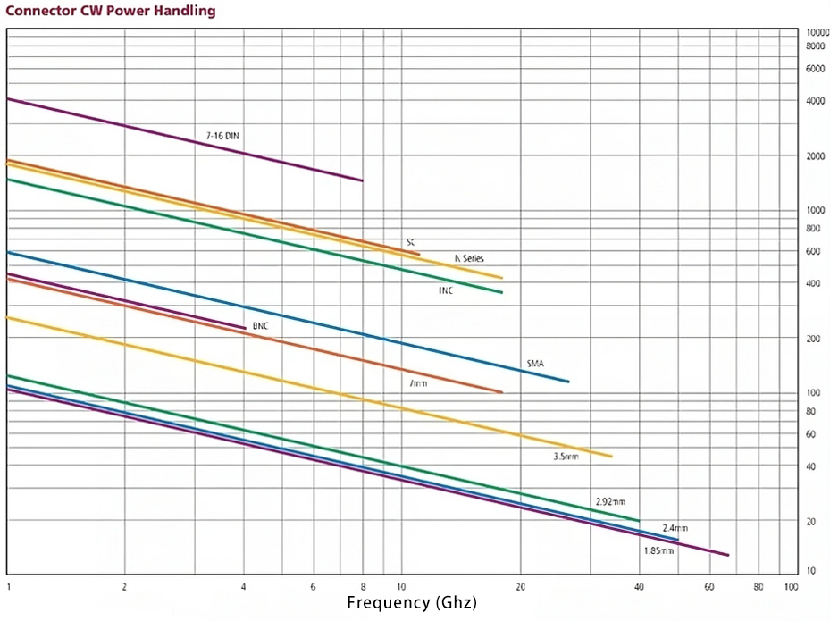
A number of factors, including connector size (including pinhole size), operating frequency, body material, dielectric material, contact reliability, contact resistance, voltage VSWR, ambient temperature, and altitude, affect the power capacity of RF coaxial connectors. The following chart illustrates the recommended power capacity values for different RF connectors at different frequencies. When designing an RF product, you should select the appropriate connector according to the product’s operating frequency and withstand power. Next, we will introduce in detail the various factors affecting the power capacity of RF coaxial connectors.
Connector Size
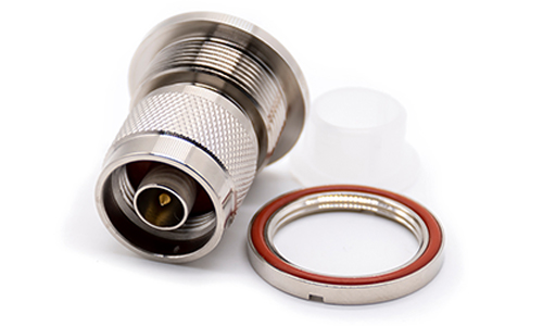
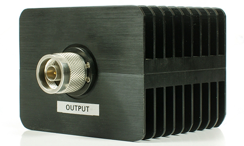
For RF signals of the same frequency, the connector with a large size has a large power tolerance. For example, the connector pinhole size relates to the current capacity of the connector, directly related to the power. In a variety of commonly used RF coaxial connectors, 7/16 , 4.3/10, N-type connector size is relatively large, the corresponding pinhole size is also larger, the general N-type connector power to withstand about 3-4 times the SMA, which is the market sales of more than 200W attenuators, loads, and other passive components most of the reasons for the N-type connector.
Operating Frequency
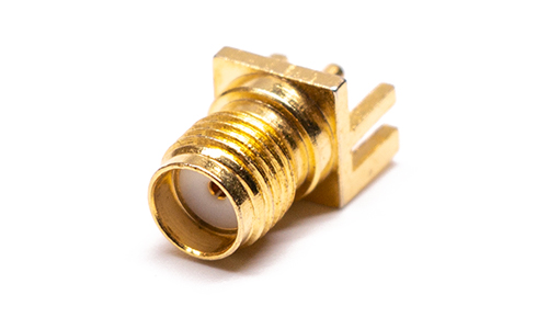
The power withstand of an RF coaxial connector increases with the signal frequency, while reducing the frequency of the transmitted signal directly leads to changes in loss and voltage VSWR, which affects the transmission power capacity. For example, a general SMA connector can withstand about 500W at 2GHz, but the average power tolerance is less than 100W at 18GHz. For frequencies higher than 18GHz, attenuators, loads, and other passive components can typically withstand an average power of 100W or less. In the millimeter wave frequency band, a 1.85mm 67GHz fixed attenuator can withstand an average power of up to 10W, while a 1.85mm 67GHz load can withstand an average power of up to 22W. 2.92mm attenuators and loads offer more choices, with an average power withstand of up to 100W.
VSWR
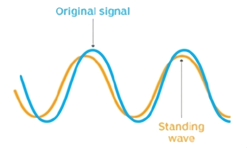
RF connector in the design of a certain electrical length, in a limited length of the line, the characteristic impedance and load impedance is not equal, from the load side of a portion of the voltage and current, is reflected back to the power supply side of the wave, known as the reflected wave; from the power supply to the load of the voltage and current is called the incident wave. The synthesized wave of the incident wave and the reflected wave is called standing wave. The ratio of the maximum and minimum values of the voltage of a standing wave is called the voltage standing wave ratio (also known as the standing wave coefficient). The reflected wave occupies the channel capacity space, which reduces the transmission power capacity.
Insertion Loss
Insertion loss (IL) is the loss of power on a line due to the introduction of an RF connector. Defined as the ratio of output power to input power. Make the connector insertion loss increased by many factors, mainly: characteristic impedance mismatch, assembly accuracy errors, fit end face clearance, axis tilt, lateral offset, eccentricity, machining accuracy and plating caused by. Due to the existence of loss so that the difference between the input and output power, will also affect the power to bear.
Barometric Pressure at Sea Level
Changes in air pressure result in changes in the dielectric constant of the air section, and at low pressures air tends to ionize and produce corona. The higher the altitude, the lower the air pressure and the lower the power capacity.
Contact Resistance
RF connector contact resistance refers to the connector insertion and closure of the internal and external conductor contact point resistance, generally at the milliohm level, the value should be as small as possible. The main purpose is to assess the mechanical properties of the contact parts and to remove measurement from the body resistance and solder joint resistance. The presence of contact resistance will cause the contact point to heat up, thus making it difficult to transmit larger power microwave signals.
Connector Materials
The same connector, using different materials, the power tolerance will be different.
Summarize
The power handling mentioned above refers to continuous wave power. If the input power is pulsed, the power handling will need to be even higher. Because these factors are uncertain and can affect each other, there is no formula for direct calculation. Therefore, individual connectors generally do not provide power capacity values. Only in the technical specifications of microwave passive devices such as attenuators and loads will the power capacity and instantaneous (less than 5 microseconds) maximum power be specified. Note that if the matching in the transmission process is not good and there is excessive standing wave, the power received on the connector may be greater than the input power. As a general rule, for safety reasons, the power loaded on the connector should not exceed half of its maximum power limit.