RF connector development overview
1939 UHF connector is the earliest RF connector;
During World War II, with the development of radar, radio and microwave communications, resulting in N, BNC, TNC and other medium-sized series;
After 1958, with the miniaturization of the whole equipment, SMA, SMB, SMC, and other miniaturized products appeared;
In 1964, the U.S. Harsh Environment standard MIL-C-39012 was developed.
In the nineties, surface mount RF coaxial connectors appeared and were used in a large number of cell phone products.
China began to develop RF connectors in the fifties;
In the sixties, set up a professional factory and began to specialize in production;
In 1972, the organization of centralized design so that the RF connector into its system. Product standards are low and not interchangeable with the international common product docking.
Since the eighties, we started to adopt international standards, according to IEC169 and MIL-C-39012, promulgated GB11313 and GJB681, so that the production and use of RF coaxial connectors gradually converge with international standards.After over a decade of efforts, the overall level of RF connectors and the gap between foreign countries is not large.
RF connector standard system
The United States is the world’s largest general-purpose RF connector manufacturing and consumer country. Its technical level is first-class, so the US Harsh Environment standard MLC39012 is considered the highest standard for RF connectors. Other advanced countries have standards such as Germany’s DIN, Britain’s BS, Japan’s JIS and IEC standards.
China’s current civilian RF coaxial connector standard is GB11313. It is copied from advanced foreign standards developed, so China’s current standards and international standards, and indicators and technical level with the advanced international level of synchronization.
RF connector technical characteristics
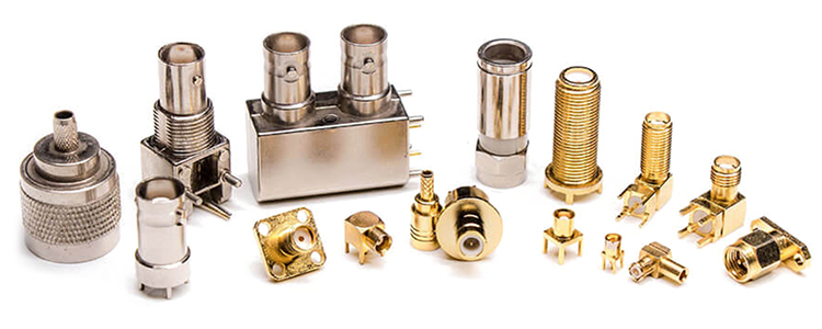
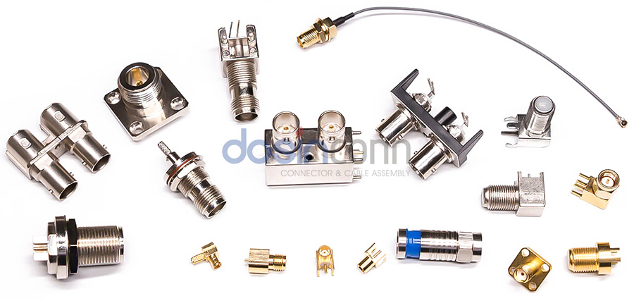
RF connector is usually mounted on the cable or installed on the instrument to achieve the electrical connection or separation of the transmission line components. It belongs to the mechatronics products. Simply put, it plays a bridging role.
A wide range of connectors, according to the technical characteristics of the different, divided by frequency Audio, Vidio, Radio, and Fiber optic four categories.The frequency range is as follows:
Audio — 20KHz or less
Video—-30MHz ~500MHz or less
Radio—-500MHz ~300GHz
Fibre—–167THz ~375THz
RF connectors refer to connectors used in the radio wave band.
Classification of RF connectors
Classification by termination method:
Connector MIL-C-39012
Adapters MIL-A-55339
Microstrip and ribbon line ML-C-83517
Classification by connection method:
Bayonet type (internal bayonet, external bayonet)
Threaded (right-hand thread, left-hand thread)
Push-in type (in-line type, with stop, self-locking type)
Classification by function:
Special type (irradiation resistant, high pressure resistant, waterproof, etc.)
Multi-function type (including filtering, phase modulation, mixing, attenuation, detection, limiting, etc.)
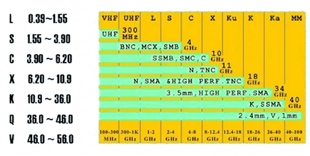
By size:
Standard (N, UHF…)
Small (BNG, TNG…)
Subminiature (SMA, SMB, SMC, MCX, BMA, SAA…)
Miniature (SSMA, SSMB, MMGX ….)
RF Connector Main Specifications
Electrical
Characteristic impedance
Characteristic impedance (Zo) is a very important basic parameter of RF connectors, which directly affects the voltage VSWR, operating band, insertion loss and other indicators.
Contact resistance
Refers to the contact point resistance in milliohm level. The value should be as small as possible. It mainly assesses the mechanical properties of the contact parts.
Insulation resistance
The main assessment of the dielectric material characteristics, structural design and the assembly process of the part’s surface clean. Poor insulation performance will produce leakage current, light noise, and serious failure to transmit signals effectively.
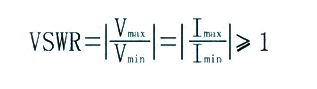
Voltage standing wave ratio (VSWR)
VSWR is the most significant value of the minimum amplitude ratio of the voltage (current) on the transmission line, is the most important electrical indicator of RF connectors, and is the main basis for measuring the performance of RF connectors.
Mechanical structure
RF connectors rely on excellent mechanical structure to ensure the electrical and use characteristics. Therefore, the design of the mechanical structure is very important. It must grasp the customer requirements to ensure the required characteristics fully.”
Engagement force and separation force
The main assessment of the connector plugging feel, threaded connectors with the engagement torque test, bayonet type with torque and force test, push-in force test
Connection mechanism torque resistance
This indicator is only applicable to threaded connectors. The main purpose is to test the strength of the connection mechanism. For small threaded connectors to achieve the target is more difficult, the need for strict control from the connection mechanism materials, processing technology and installation process.
Plugging characteristics
Plugging characteristics is mainly through mechanical methods to check the elasticity of the elastic jack. Its performance is directly related to contact resistance and connector durability.
Centre contact fixed
Regardless of the connector, the central contact is connected to the cable core, microstrip, or another conductor. When the connector is used in the center of the contact will be subject to the axial push and pull. The role of torque, if the center of the contact is not well fixed, will lead to the end of the connection point is too much force and loosened or broken.
Environmental aspects
Sealing
Waterproof seal: to prevent water or moisture from entering at low pressure.
Gas seal: There is a specific leakage rate indicator, and the connector needs to be glass or ceramic sintered.
Vibration
Prevent connectors from transient breakage or cosmetic, mechanical damage under vibrating environmental conditions.
Shock
To test the connector’s shock resistance, prevent the connector in transport, fieldwork or careless handling of the damage caused by the ring.
Temperature shock
This test determines the ability of the connector to withstand shock during high to low temperatures. Temperature shock may cause the potting part of the peeling, crack, insulation degradation, bad shell cracking, etc.
Humidity resistance
The moisture test aims to evaluate the connectors and their materials to withstand the ageing effects caused by high temperature and high heat conditions. Poor humidity resistance of the connector is the main performance of the medium voltage, insulation resistance decline, surface ageing, and even cracking.
Salt spray
This test mainly simulates the coastal working environment conditions and the connector corrosion resistance. The actual main test is the quality of the coating.
Connector selection and use
Selecting the appropriate RF connector is recommended from the following aspects of a comprehensive consideration, one by one elimination, and finally the best selection of the required products.
Selected by the use of the requirements of the characteristic impedance, operating frequency to meet the requirements of RF connectors.
According to the size of the transmission power, insertion loss, shielding requirements to select the appropriate RF connector and the appropriate cable.
Combined with the size of the use of space, the frequency of plugging and unplugging and use of the environment to determine the RF connector connection.
According to the use of space to determine the fixing method (flange, nut, welding).
Determine the cable termination side.
Determine the connector form factor according to the use requirements.
Users must be familiar with the performance of the selected product, strictly according to the rated conditions of use, any overload use is likely to RF connector failure. For cable connectors, special attention should be paid to the cable assembly, should be provided by the supplier’s assembly instructions for assembly, if improperly assembled, even if the cable and connector performance is very good, the component performance may be very poor.