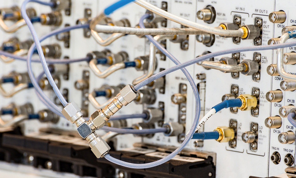
RF cable assembly has the characteristics of small loss, small radiation and good electromagnetic compatibility, and can work in a higher frequency range. It is relatively easy to wire throughout the facility and has a high degree of practicality and maintainability. In the whole process of product realization, from RF connector and cable assembly to the wiring of the whole machine, no matter which link has problems, it will lead to the performance of the cable assembly cannot meet the design requirements, thus the whole link caused by the impact. Therefore, analysis of RF cable assembly from connector assembly to wiring the whole process, to grasp the key points of RF cable assembly use, is one of the key factors to ensure the performance of the link.
Common forms and causes of failure
open circuit
Generally, one uses a soldered construction to connect the RF cable core to the internal conductors of the connector. If the solder joint breaks, it leads to intermittent or complete loss of cable signal. The main causes of poor soldering of the core and inner conductor are: improper stripping of the core, resulting in damage before soldering; oxidation of the core or inner conductor and poor solder wetting; and insufficient tin fill, resulting in an unreliable connection.
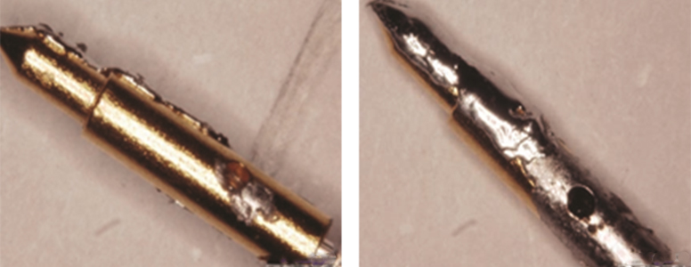
short circuit
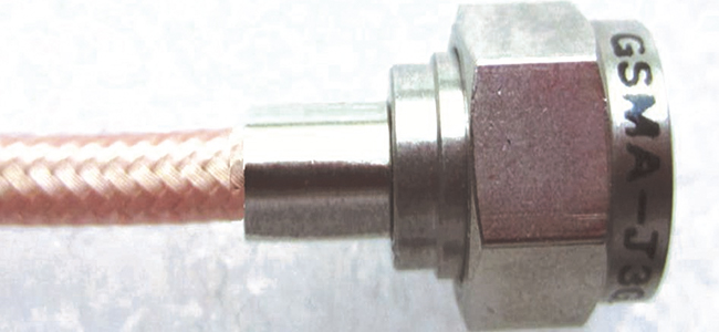
Insufficient insulation or shorting of the inner and outer conductors of the RF connector, resulting in direct grounding of the signal. Normal RF connectors between the inner and outer conductors have insulation media to provide protection, generally PTFE. Take SMA RF cable as an example, qualified SMA RF cable tested under 500V megohmmeter, the insulation resistance between the inner and outer conductors is generally greater than 500MΩ. short circuit mainly for the following two reasons: improper welding of the inner conductor or too much tin filling, resulting in solder tumor resulting in reduced insulation performance; braided outer conductor improperly handled, resulting in burs, resulting in a short circuit between the inner and outer conductors, etc.
Poor contact
Poor contact mainly refers to the cable inner conductor installation is not in place or the outer conductor grounding is not secure to bring the cable VSWR and insertion loss and other performance instability, especially in dynamic conditions. The causes of poor contact are generally:
Improper and incorrect assembly of connectors leads to loose connections, resulting in poor electrical performance due to poor contact.
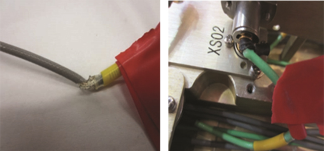
Poor grounding caused by damage to the outer shield of the cable. In a more confined space, the connector or cable is pressurized causing the shield to wear and the solder joint to break, which directly leads to cable failure.
RF connectors and cable assembly soldering well, not arbitrarily bend and folded placed. Different types of RF cables have a minimum turning radius requirements, if the cable installation cannot meet the minimum turning radius requirements, the impact on the transmission of RF signals, resulting in electrical performance damage.
Quality Assurance Measures
RF cable assembly performance indicators are: insertion loss, VSWR and phase. Except for the phase index, which requires constant assembly testing, the insertion loss and VSWR are relatively stable under normal process flow. The assembly process of the wire, stripping quality, connector and cable welding level, cable wiring quality, etc. will have a direct impact on the insertion loss and VSWR performance. Therefore, controlling all aspects of RF cable from connector assembly to cable wiring and clarifying the details and requirements of each stage of operation is the key to stabilizing the quality of cable assemblies.
Cable stripping
The stripping operation of the RF coaxial cable is one of the key factors affecting the performance of the cable. To ensure the accuracy of the stripping head size and coaxiality, operators should avoid manual methods of cutting and stripping as much as possible and instead utilize automatic stripping equipment in their processing methods. The cut inner conductor, outer conductor and insulation media end face must be flat and perpendicular to the cable axially to avoid defects such as broken core, burr and deformation to ensure the stability of the cable performance.
Inner conductor welding
When soldering the inner conductor to the core wire, it is necessary to clamp the inner conductor with tooling and select the proper soldering temperature. To enhance the solderability of the inner conductor and prevent false solder defects during direct soldering, it is necessary to tin the tail of the inner conductor before soldering. This will ensure the formation of a sufficient solder layer.
To ensure the welding is reliable, it is recommended to gently rotate or plug and unplug the cable core during the process. This ensures that the solder fully infiltrates the inner conductor. If there are not enough solders, a small amount can be added through the observation hole of the inner conductor. Once welding is complete, it is crucial to check the quality carefully. The core wire should exceed the observation hole, the solder in the hole should not be higher than the outer surface, and there should be no defects such as burrs, pulled tips, or weld tumors.
Outer conductor assembly
Solder
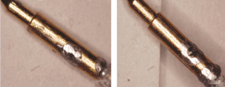
People generally choose induction welding or resistance welding equipment to ensure uniform heating of the cable welding parts, good solder infiltration, and reliable welding. For example, when handling SMA connectors, operators should first assemble the outer conductor with the soldered inner conductor. Check to ensure that the step surface of the inner conductor is flush with the insulation medium of the outer conductor. In the coaxial cable outer conductor pre-set a 6 ~ 8 turns of solder ring, and the connector clamped on the welding equipment, the use of high-frequency induction or resistance welding two electrodes generated by the heat will melt the solder ring. When the visual inspection to the solder wire completely melted, solder fully wetted, stop heating, natural cooling alcohol cotton cleaning solder joints.
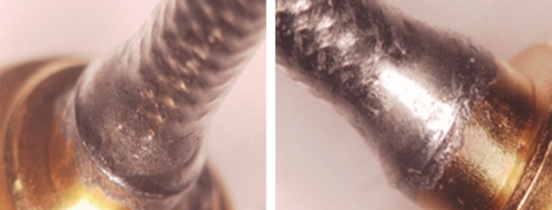
As shown above, good shape of outer conductor, good solder spreading form, lupine spreading to the end face of the connector tailstock. The surface of the solder joint is smooth and free of defects such as burrs, pinholes and slag.
Crimp
Before crimping, wrap the shield evenly around the connector crimp step and push the crimp steel ring to the root of the shell until all shields are crimped. Then use diagonal pliers to cut off the excess shielding layer, with a special crimping die in a crimping cycle, the steel ring crimp hexagonal. Remember that a crimping molding, eliminate repeated crimping, the requirements of the steel circle and cable shield crimping firm, no loosening, no cracking defects.
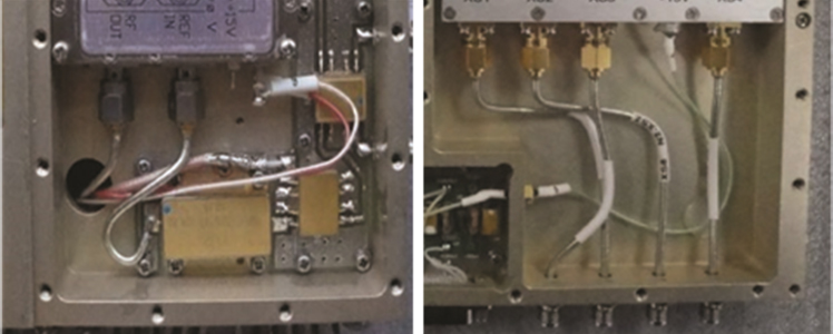
Cable Wiring
RF cable assembly installation, structural design must fully consider the special characteristics of the RF cable assembly, leaving sufficient installation space. The bending radius for RF cable wiring must be strictly adhered to, particularly in tight spaces during installation of RF cable assemblies. Inadequate consideration of design and insufficient installation space can result in failure to meet minimum turning radius requirements, leading to long-term stress that may damage the outer shield or cause cracked solder joints at the cable root due to pressure. According to experience, the relative insurance turning radius requirements are: semi-rigid (semi-flexible) cable shall not be less than 10 times the diameter of the cable, flexible RF cable shall not be less than 5 times the diameter of the cable.
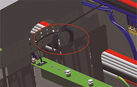
In special structures such as cabinets, the RF coaxial cable length release must also be considered, and the use of bobbin coiling of the cable is generally recommended. Even if the space does not allow the arrangement of winding tray, it must also leave sufficient space for the redundant RF cable coiling, and reliable fixing of the RF cable to avoid the use of stress caused by RF cable breakage and other failures.
When installing semi-rigid (semi-flexible) cables, it is important to pay attention to the cable shaping. Operators should use tools to bend the cable into the desired shape, ensuring it meets the requirements of the connector socket position. The cable should meet the minimum bending radius and be properly formed. Even with small dimensional errors, forcing a connection can cause the connector root to bear a certain amount of stress, which may cause the outer conductor root solder joint to crack when subjected to environmental factors such as temperature and vibration in the later stage.on in the later stage.
Connector Fastening
To fasten RF connector connections, it is common practice to utilize a torque wrench that adheres to the relevant standards and the recommendations provided by the manufacturer. For SMA-type connectors, the recommended tightening torque typically ranges from 0.79 to 1.13 N-m. SSMA connector tightening torque is generally 0.6 ~ 0.8 N-m. Non-standard operation will bring about false tightening or over-tightening between the connector and the socket, which will cause adverse effects on the performance of the cable and future rework and repair. The adverse impact on the performance of the cable and future rework and repair.
Conclusion
The failure of any one RF cable assembly will have a certain impact on the performance of the whole system, and stable and reliable cable assembly and wiring process technology is the primary guarantee of product quality. To ensure the quality of RF coaxial cable assemblies, it is essential to enforce rigorous controls over the cable stripping process, inner and outer conductor welding (crimping), and the installation of RF cable assemblies. Operators must standardize and execute each of these key steps with precision to guarantee the accuracy of the entire operation and ensure the overall excellence of the final product.