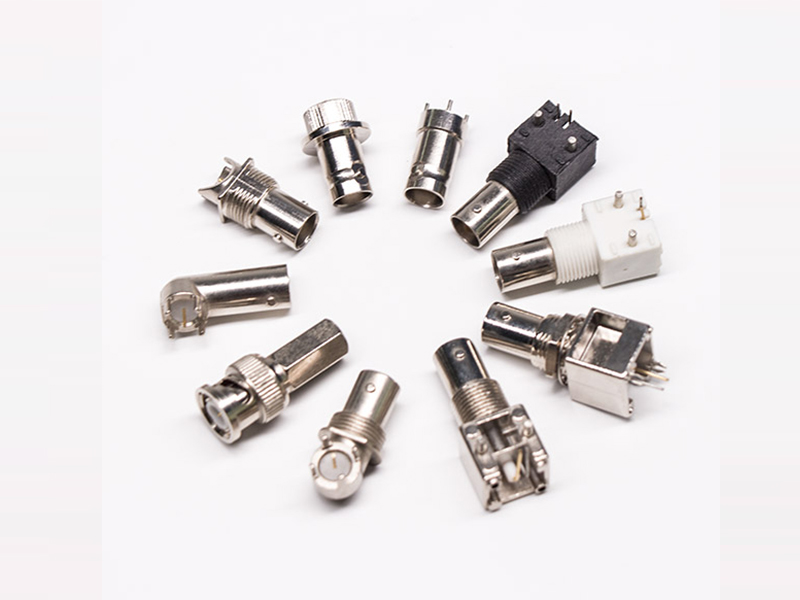
Types of BNC Connectors
BNC connectors, short for Bayonet Neill-Concelman connectors, are commonly used RF terminal coaxial cable terminators in security monitoring and audio-video engineering. They consist of three main parts: a center pin, a jacket, and a card seat. BNC connectors come in two main types:
Soldering Type BNC Connectors: Soldering-type BNC connectors, as the name suggests, are affixed using soldering iron and solder. This type is prevalent in China, categorized into British and American variations based on their shapes, and into cored and zinc alloy based on materials.
Solder-free BNC connectors come in four primary types:
Screw-tightened connectors
Straight screw-type connectors
Cold press-type connectors
Extrusion-type connectors

Installation of BNC Connectors
Stripping
Begin by stripping the coaxial cable. Peel off the outer protective rubber carefully, leaving approximately 1.5cm exposed. Take care not to damage the metal shielding wire. Next, strip the milky white transparent insulating layer surrounding the core wire by about 0.6cm to expose the core wire.
Connect the Core Wire
The BNC connector comprises a connector body, a shielded metal sleeve, and a core wire pin. Insert the stripped core wire into the core wire pin’s small hole, ensuring a secure fit. Use the small slot on the front of a specialized wire clamp to tighten the core wire within the small hole.
Solder the Core Wire
If desired, use an electric soldering iron to solder the core wire to the core wire pin. Add a small amount of rosin powder or neutral flux into the small hole at the end of the core wire pin before soldering. Be cautious not to let the solder extend beyond the core wire pin’s outer surface to prevent damage.
Assemble the BNC Connector
Once the core wire is connected, insert the shielded metal sleeve into the coaxial cable. Insert the core wire pin from the BNC connector body’s tail hole, allowing it to protrude from the front end. Push the metal sleeve forward to secure the outer metal shielding wire to the cylinder at the end of the BNC connector body.
Crimp the Sleeve
Ensure that the sleeve maintains good contact with the metal shielded wire, then securely clamp it using the hexagonal bayonet on the caliper to form a hexagonal shape.
Repeat the Process
Repeat the above steps to install a BNC connector on the other end of the coaxial cable. Before use, it’s advisable to check with a multimeter for any open circuits or short circuits, as these can lead to communication failures and potential damage to network equipment.
Additional Note
An alternative method involves using a small screwdriver and electrician’s pliers. After stripping the wire as described earlier, insert the core wire into the core wire fixing hole, secure it with a small screwdriver, and twist the outer metal shielding wires together. Then, use electrician’s pliers to secure the shielded wire within the fixing sleeve, and finally, attach the tail metal to the BNC connector body.
With these steps, you can successfully install BNC connectors on coaxial cables for your various RF applications.