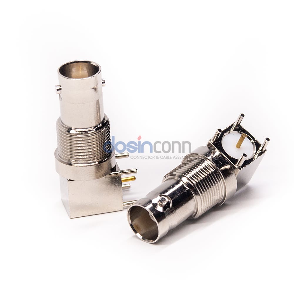
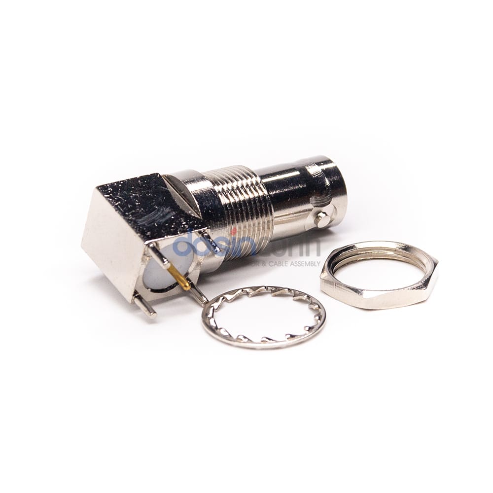
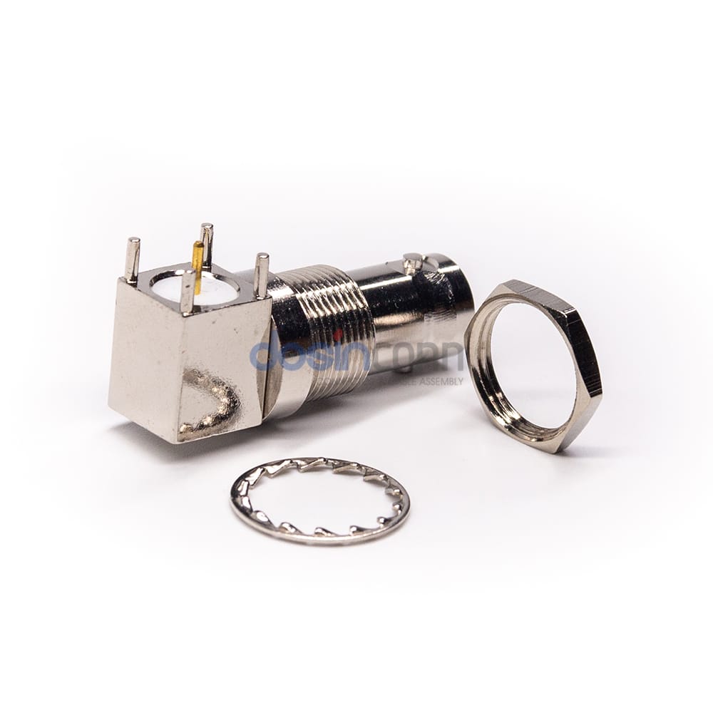
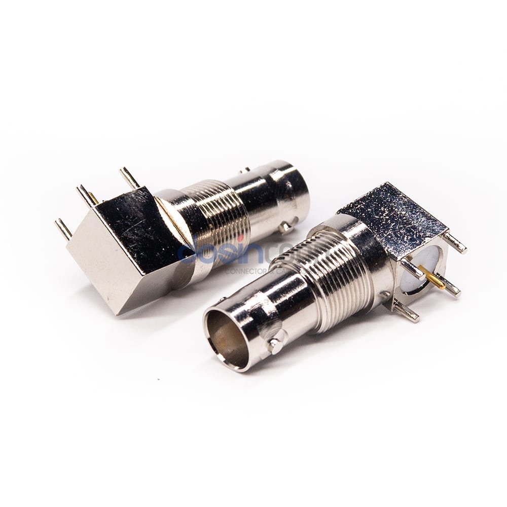
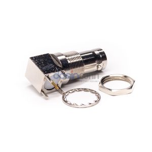
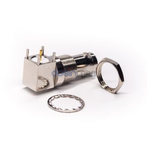
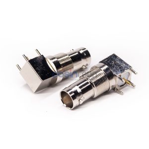
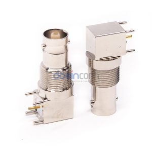
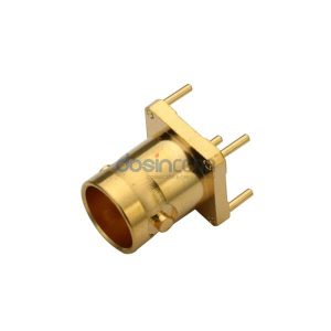
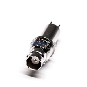
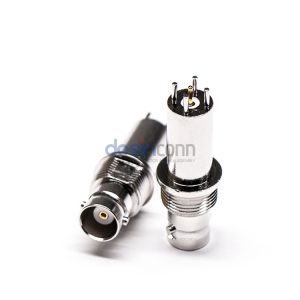
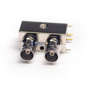
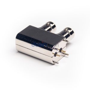
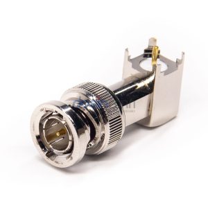
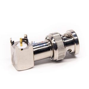
Coaxial Connector BNC Right Angle Jack Female Pin Panel Mount Bulkhead

Part NO.: RHT-610-0031 Category:

Authorized Sellers

  • Bayonet coupling mechanism provides positive, quick mating and un-mating
  • 50 and 75 ohm impedance designs allow customers to match impedance to system requirements
  • Connectors are available for industrial and commercial applications
  • Designs available for many common BNC coaxial cable types
  • BNC female and male configurations

BNC RF Connectors are used in surveillance projects for the output of camera equipment when the wire and the camera connection head. It consists of five independent signal connectors for RGB tri-color signals and line synchronization and field synchronization.

BNC RF connectors isolate the video input signal, reducing mutual interference between signals and increasing signal bandwidth to get the best signal response. Because the coaxial cable is a shielded cable with the advantages of long transmission distance and signal stability. BNC RF Connectors are now also used in a large number of communication systems.
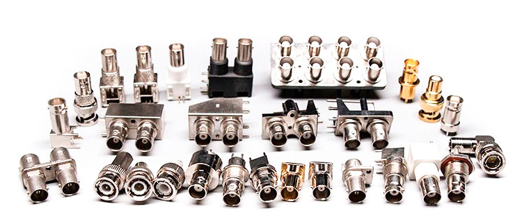
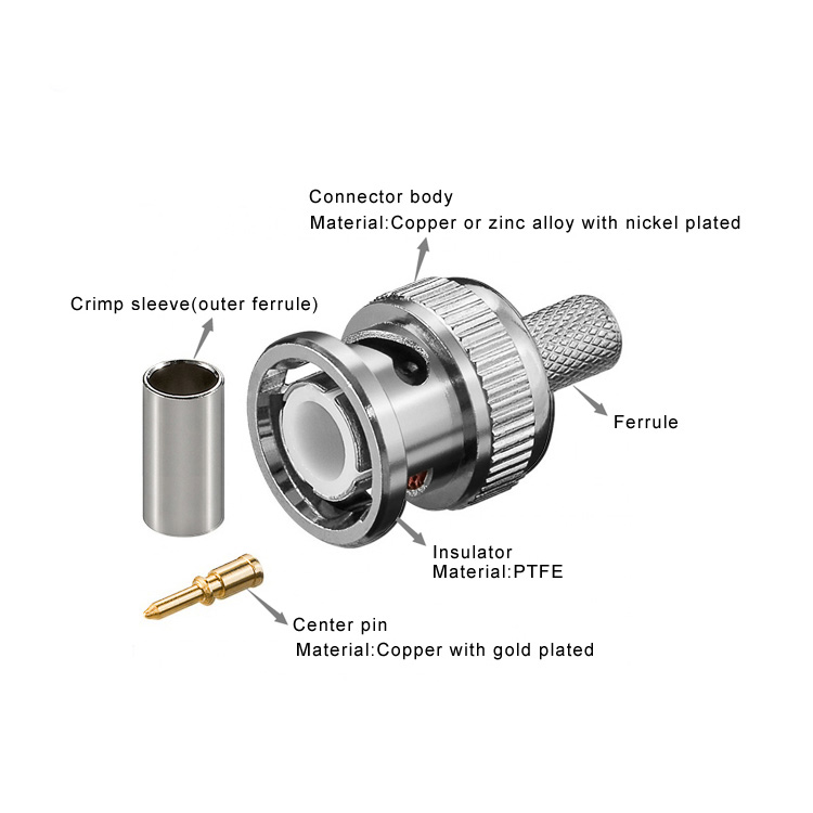
BNC connector-1

BNC Detail Show

BNC Cable Connector

BNC-Cable-connector


BNC PCB/Panel Connector
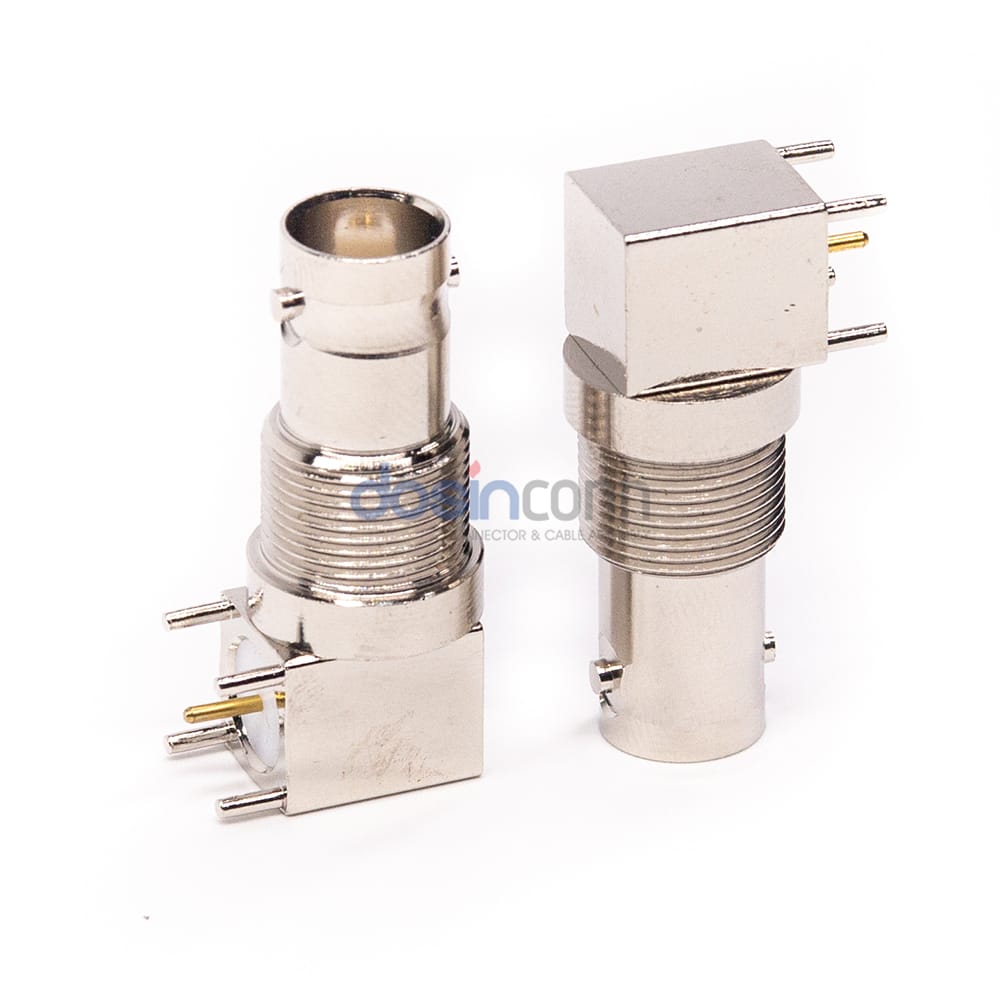
BNC-Panel-connector

Basic Specifications

RF Series

BNC Type

Connector Type

Jack

Contact Type

Female Pin

Orientation

Right Angle

Number of Ports

Mounting Type

Mounting Feature

Insulator Material

Teflon White

Body Material

Body Plating

Nickel Plating

Contact Material

Copper

Contact Plating

Gold Plating

Electrical Specifications

Impedance

50 Ξ©

Frequency Range

0~4 GHz for 50 ohm

VSWR

R/A type ≦ 1.30/3GHz, Straight type ≦ 1.22/3GHz

Dielectric Withstanding Voltage

1500 V rms

Working Voltage

500 V rms

Center Contact Resistance

≦ 1.5 MΞ© (Milliohms Max.)

Outer Contact Resistance

≦ 2.0 MΞ© (Milliohms Max.)

Insultation Resistance

≧ 5 Γ— 10Β³ MΞ© (Milliohms min.)

Mechanical Specifications

Fastening Type

Bayonet

Contact Retention

6 lbs min.

Mating Durability

≧ 500 Cycles

Environmental Specifications

Environmental Characteristics

POM -40℃~+60℃, Teflon -55℃~+155℃

Coupling Nut Retention

100 lbs. min.

Vibration

MIL-STD-202 Meth. 204

Corrosion Resistance

MIL-STD-202 Meth. 101

RF Series

BNC Type

Connector Type

Jack

Contact Type

Female Pin

Orientation

Right Angle

Number of Ports

Mounting Type

Mounting Feature

Impedance

50 Ξ©

Insulator Material

Teflon White

Body Material

Body Plating

Nickel Plating

Contact Material

Copper

Contact Plating

Gold Plating

Frequency Range

0~4 GHz for 50 ohm

VSWR

R/A type ≦ 1.30/3GHz, Straight type ≦ 1.22/3GHz

Dielectric Withstanding Voltage

1500 V rms

Working Voltage

500 V rms

Center Contact Resistance

≦ 1.5 MΞ© (Milliohms Max.)

Outer Contact Resistance

≦ 2.0 MΞ© (Milliohms Max.)

Insultation Resistance

≧ 5 Γ— 10Β³ MΞ© (Milliohms min.)

Fastening Type

Bayonet

Contact Retention

6 lbs min.

Mating Durability

≧ 500 Cycles

Environmental Characteristics

POM -40℃~+60℃, Teflon -55℃~+155℃

Coupling Nut Retention

100 lbs. min.

Vibration

MIL-STD-202 Meth. 204

Corrosion Resistance

MIL-STD-202 Meth. 101


Download Drawing

Download Test Report

Declaration of Conformity